Blender Tutorial - Pixelate Node
Recently I participated in a friendly rendering competition, in which each artist was given a span of ten minutes to produce a complete image using only the Blender software. That meant no image editing programs, no access to stock photos for image mapping, and no complex materials or scenes. It was a really fun challenge, and I would encourage anyone interested in CGI work to try it out - either in a competition or just as a personal challenge. But I digress...
The reason I mention this is that some of the other participants were curious about my method for generating a simple nighttime cityscape. The usual method of producing lit windows in office buildings is to download or produce black-and-white maps that are used to add an emission shader to certain parts of the model - but as I wrote above image maps were not allowed in this competition.
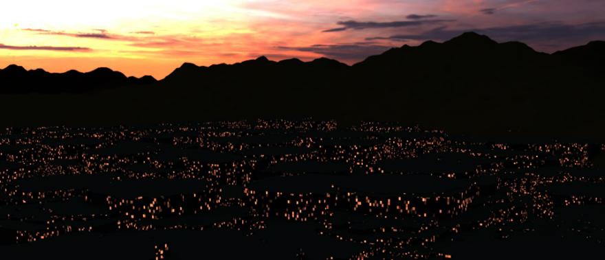
The answer is to use a Pixelate node. The Pixelate node divides the mesh it is applied to into rectangular squares, and then by adding a Texture:Noise node each square is assigned a random colour. Connecting the output of the Texture:Noise node to a colour ramp with suitable blends of black and yellow/orange then produces squares with different shades of yellow/orange. Connecting this to an Emission Shader then produces a decent lit window effect when applied to a basic building mesh.
The only problem is that, at the time of this writing Blender Cycles does not contain a Pixelate Node!
And so we arrive at the point of this tutorial - how to create your own Pixelate Node. I will present this in several stages, with each stage adding more customization to the node.
Step 1: Create a Node Group, with a single vector input and a single vector output. Connect the input to a SeparateXYZ Node, to generate separate channels for each coordinate. Connect the ouput to a CombineXYZ Node, so that the final result will be a vector again.
Step 2: Now we need to divide each component of the vector in to unit length sections. Connect the X output of the SeparateXYZ Node to a Math:Round node. This will remove the fractional part of the component, and output only an integer value. Connect this output to the CombineXYZ Node, and then repeat this step for the Y and Z components. (It is worth mentioning here that for some odd reason the Round node includes a second input that is ignored by the node. Just ignore it)
This is the basic Pixelate Node, but it is far too basic to be of any use. So now we will add the next level of control.
Step 3: In the Input Node, add four new inputs labelled Scale, ScaleX, ScaleY,ScaleZ and give them each a default value of 1.00. Into each connection from the SeparateXYZ Node to the Math:Round nodes, add two Math:Multiply nodes. Connect the Scale input to the first Multiply node of each connection. Connect the ScaleX input to the second Multiply node in the X connection, and do the same for ScaleY and ScaleZ in the Y and Z connections.
This will allow us to change the size of the pixels, and to provide separate scaling for each direction. In the city example above, the Scale parameter is used to make the windows smaller, and the ScaleZ parameter changed them from stretched vertical windows to (rough) squares.
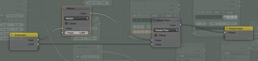
Step 4: Another customization that I added is to add three extra Outputs to the Output node, and connect the outputs of the three Multiply Nodes to them. I also added three Math:Add Nodes to generate a slight offset that moves the boundary. This is not usually needed, but it does allow us to access the three components of the vector without the rounding factor. In my city lights example, I used these outputs together with Math:Modulus and Math:GreaterThan nodes to produce a frame around the windows. This helps to divide different lit windows and create a more clear outline of each square.
For completeness, I have also included my Border Node setup below, but it is a separate topic. Basically this node takes a real number, uses the Math:Modulus node to remove the integer component, and then the Math:GreaterNode to set the output to 0 or 1 depending on the value of the fractional part of the input. Plugging this output into the Fac input of a MixShader allows us to add a border to the lit windows.
The rest of the city lights scene is just the usual methods of Blender, and so I won't go over them in detail. It is just a Particle:Hair system, with a cube object that has the lit windows material I outlined above. And while this is not good enough for foreground buildings or high detail renderings, for distant cities and backdrops it works just fine.
So I hope you enjoyed this brief tutorial, and find many uses for the Pixelate Node in your own artwork!